re:invent 2019 - IoTanium by Onica: Unboxing and Assembly
I attended re:Invent 2019 at Las Vegas, NV and one of the vendors, Onica, had a chance to win their IoTanium Dev Kit by (1) making motions and capturing that motion; (2) upload the captured motion to a ML algorithm to (3) generate a model with the captured motion and associate that with movement and action to then (4) play a game and make motions / actions that would move an avatar in the game.

Upon opening the box, I am greeted immediately with instructions for construction. You will need a Phillips screwdriver to complete the assembly.

Two main pouches are in the box, one with the microcontroller dev board and the breakout board, the other with a breadboard, screws, risers and some electronics.

Here we have the microcontroller (ESP32) and the breakout board. The goal with Onica providing this dev kit is that it adds an easy way to connect sensors and other external devices to the ESP32. And then the breakout board enables simple connectivity to a breadboard (shown later).

From the 2nd parts bag I removed the risers and the screws that will be used to assemble the two boards.
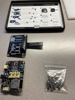
Always check to make sure that you have a correct inventory when assembling something (saves from frustration later - in this case all the pieces were there).


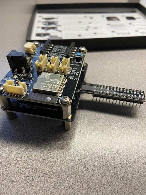
I used the female riser along with a screw and attached it to the dev board. Note that the pins will need to be on the bottom (for connectivity to the breakout board).

Completed assembly of the female risers and the associated screws.

Completed assembly of the dev board (flipped over) to show how the pins will be inserted into the breakout board.

Connecting the dev board to the breakout board. It takes a firm push to have the pins seated.

Then I took the remaining 4 male risers and screwed the boards together.

Completed assembly of the dev board and breakout board.

Take the time to make sure the pins are lined up with each of the sockets in the breadboard. I had one pin that was slightly bent so I had move it to the correct spot and then I was able to successfully push the breakout board pins into the breadboard.


Completed assembly and then I opened the electronics bag to see what I would be working with from a project standpoint.

So after 3 tries, I finally completed the exercise. I was most likely not consistent in my motions and it was hard for the model to understand what I was trying to accomplish. But I did it! :)
As a result, I received a t-shirt and their IoTanium Dev Kit. I thought in this post I'd capture the unboxing of the Dev Kit and then in subsequent blog posts, show some projects that can be completed with this Dev Kit.
The Dev Kit comes in a basic black box, filled with parts and electronic bits for assembly.

Upon opening the box, I am greeted immediately with instructions for construction. You will need a Phillips screwdriver to complete the assembly.

Two main pouches are in the box, one with the microcontroller dev board and the breakout board, the other with a breadboard, screws, risers and some electronics.

Here we have the microcontroller (ESP32) and the breakout board. The goal with Onica providing this dev kit is that it adds an easy way to connect sensors and other external devices to the ESP32. And then the breakout board enables simple connectivity to a breadboard (shown later).

From the 2nd parts bag I removed the risers and the screws that will be used to assemble the two boards.

Always check to make sure that you have a correct inventory when assembling something (saves from frustration later - in this case all the pieces were there).


I used the female riser along with a screw and attached it to the dev board. Note that the pins will need to be on the bottom (for connectivity to the breakout board).

Completed assembly of the female risers and the associated screws.

Completed assembly of the dev board (flipped over) to show how the pins will be inserted into the breakout board.

Connecting the dev board to the breakout board. It takes a firm push to have the pins seated.

Then I took the remaining 4 male risers and screwed the boards together.

Completed assembly of the dev board and breakout board.
Take the time to make sure the pins are lined up with each of the sockets in the breadboard. I had one pin that was slightly bent so I had move it to the correct spot and then I was able to successfully push the breakout board pins into the breadboard.


Completed assembly and then I opened the electronics bag to see what I would be working with from a project standpoint.

This completes the unboxing and assembly of the Onica IoTanium Dev Kit.
Stay tuned for my next blog post where I connect the dev board to AWS IoT. Future posts will include a walkthrough of the features of the dev board, connecting electronics to the board and discussing potential applications.
-brian
Note: I am not being compensated by Onica / Rackspace for this blog post, nor does this post constitute an endorsement of this product by me or my employer. I share my experiences in the hopes of educating and informing others about Internet of Things (IoT).


